Gear Geometry
Patch Kessler
2025.01.01
I’m writing up these notes because perfect is the enemy of good. For years now, I’ve been planning an interactive website to showcase beautiful results related to the theory of gearing. I've even gone so far as to obtain www.geargeometry.com as a host domain. One thing has led to another however, and the website still isn’t built. All the while, every couple of years I find myself designing a new thing with gears, and I find myself needing (these) practical working notes. My hope is that these notes are useful (or at least entertaining) to more people than just myself. Please enjoy!
Involute Gearing with Parallel Axes
The key picture to keep in mind when gear axes are parallel is of two disks connected by an unstretchable string.
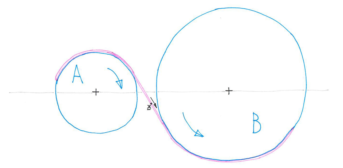
Imagine B pulling A in a steady motion. We build gear teeth that cause A and B to engage as if they were connected in this way.
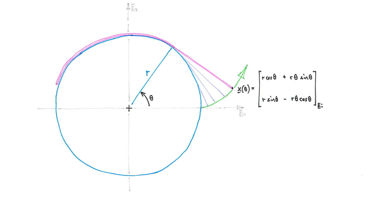
As A and B rotate, we see the point x moving along the line of the string. At the same time, from the perspective of the (rotating) disk A, the string is unwrapping from disk A, and the point x is tracing out a special curve known as an involute, shown below in green. This curve is the working surface of the gear tooth.
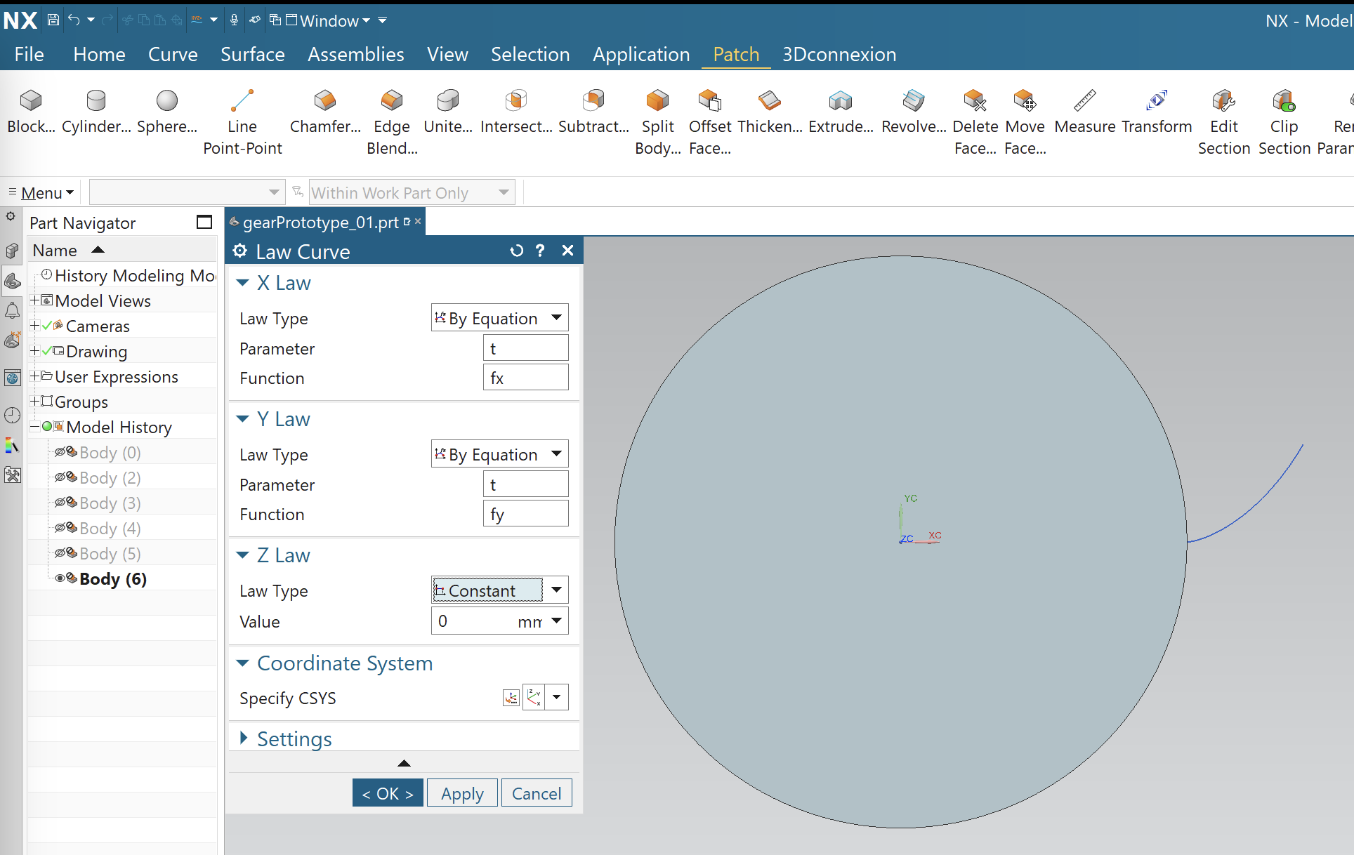
We get this equation into CAD by going to Menu > Tools > Utilities > Expressions. (My CAD notes are for Siemens NX.)

This gives you an "expressions" panel where you can type in mathematical formulae. Here’s what this panel looks like after I've typed in the equations for an involute coming off a disk with radius 8.0.

The panel is a bit clunky and requires some patience to use. Trig function arguments are in degrees, and the independent variable t goes from 0 to 1 regardless of the value you assign to it. We get the trig function arguments to go from 0 to 60 (degrees) by feeding them t*60. The corresponding angle in radians is t*60*pi/180, which is roughly t*1.04719755.
After adding t, fx, and fy to the expressions panel, we insert a so-called law curve into our workspace. The following view shows this curve in blue, along with a 16mm diameter cylinder that I also created.
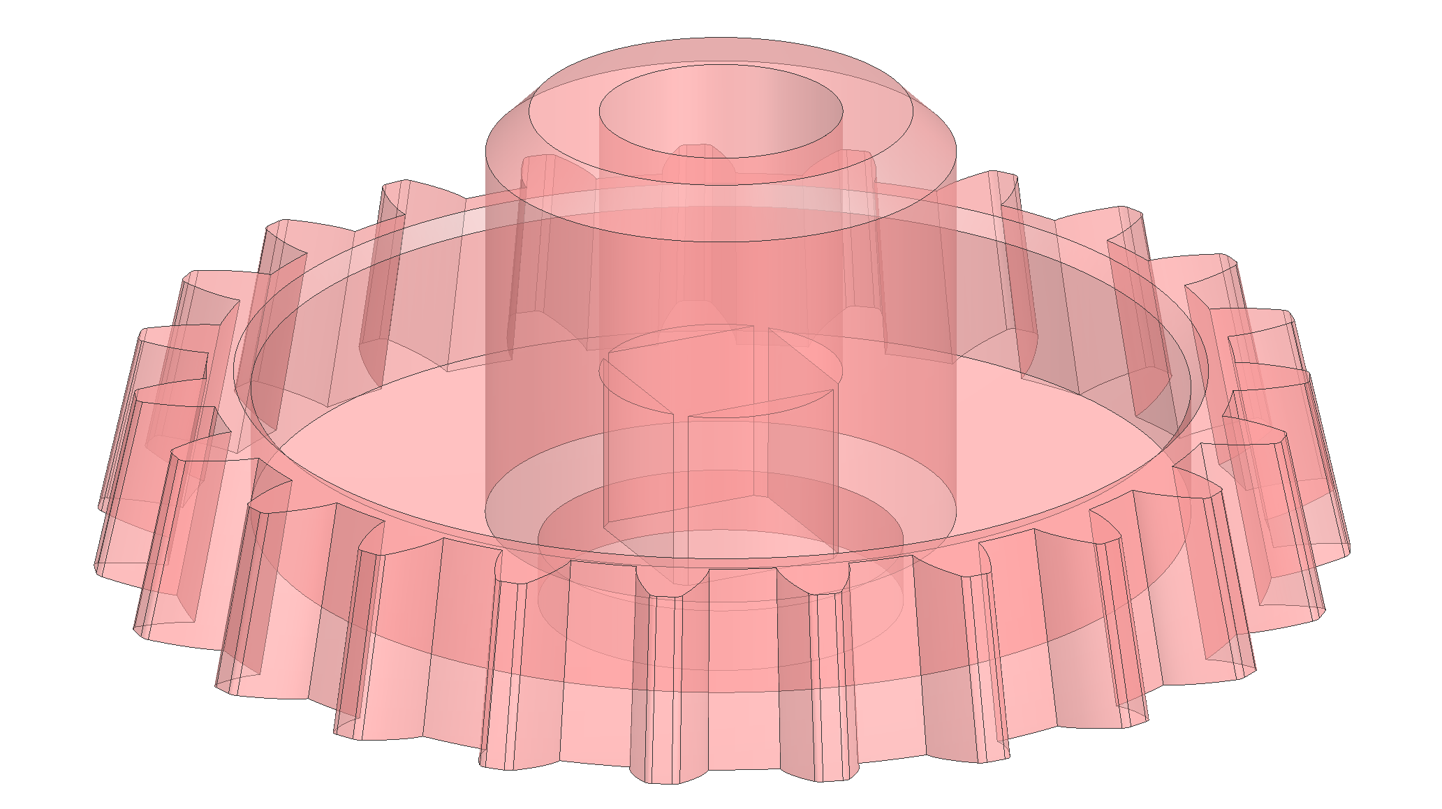
We use the law curve to split a solid body (with the split body tool), giving us the working face of one tooth. We then use reflection and rotation to create the full gear.
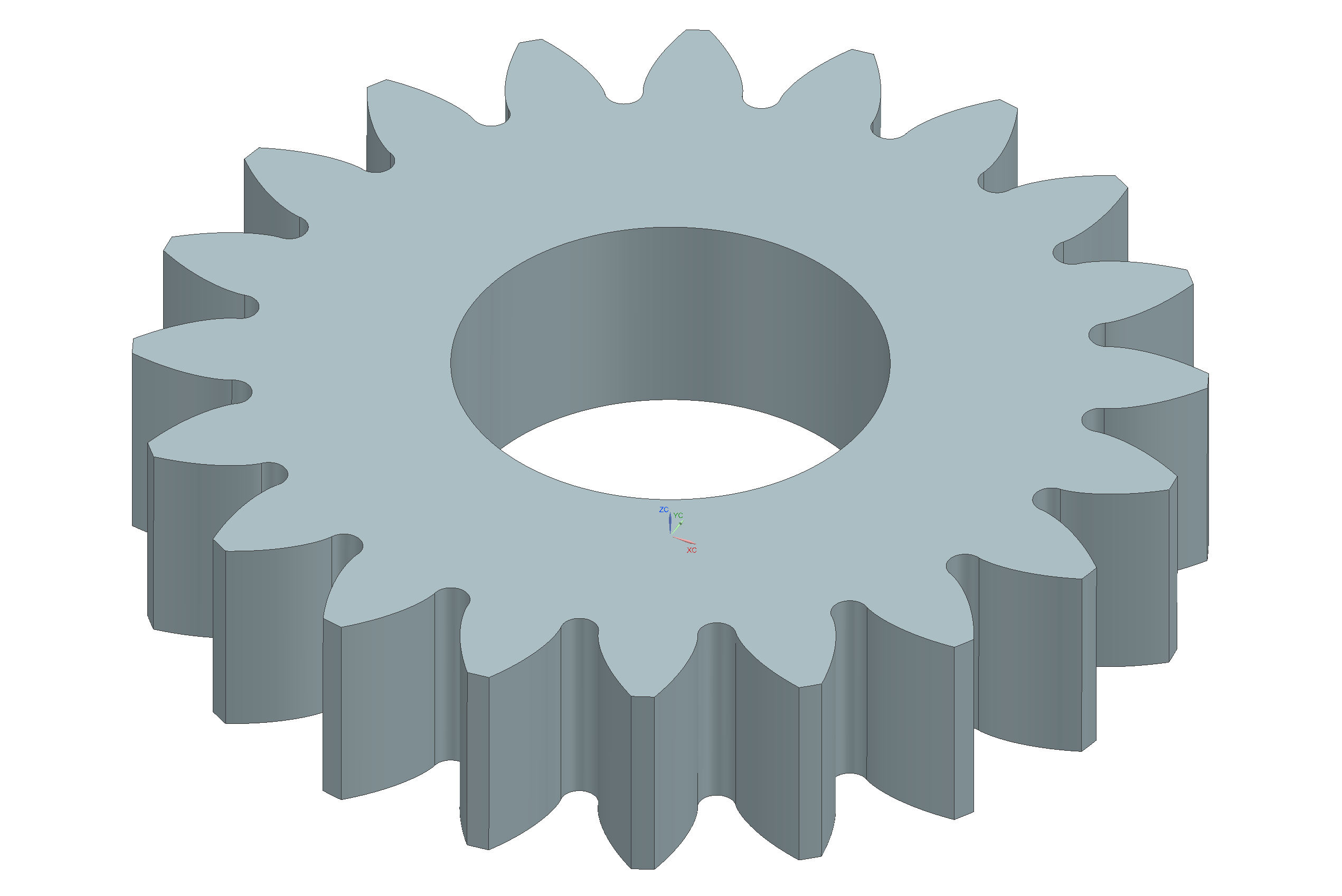
We keep an eye on the thickness of the gear teeth, because they will break if they are too thin. We also monitor the amount of backlash. Backlash needs to be appreciably greater than zero for smooth running (backlash accommodates manufacturing imperfections).
Involute Gearing with Intersecting Axes
The key picture to keep in mind when gear axes intersect is of the paper wrapper around an ice cream cone.

Unwrapping the paper from the cone gives a flat (annular) piece of paper which can then be wrapped around a second cone.
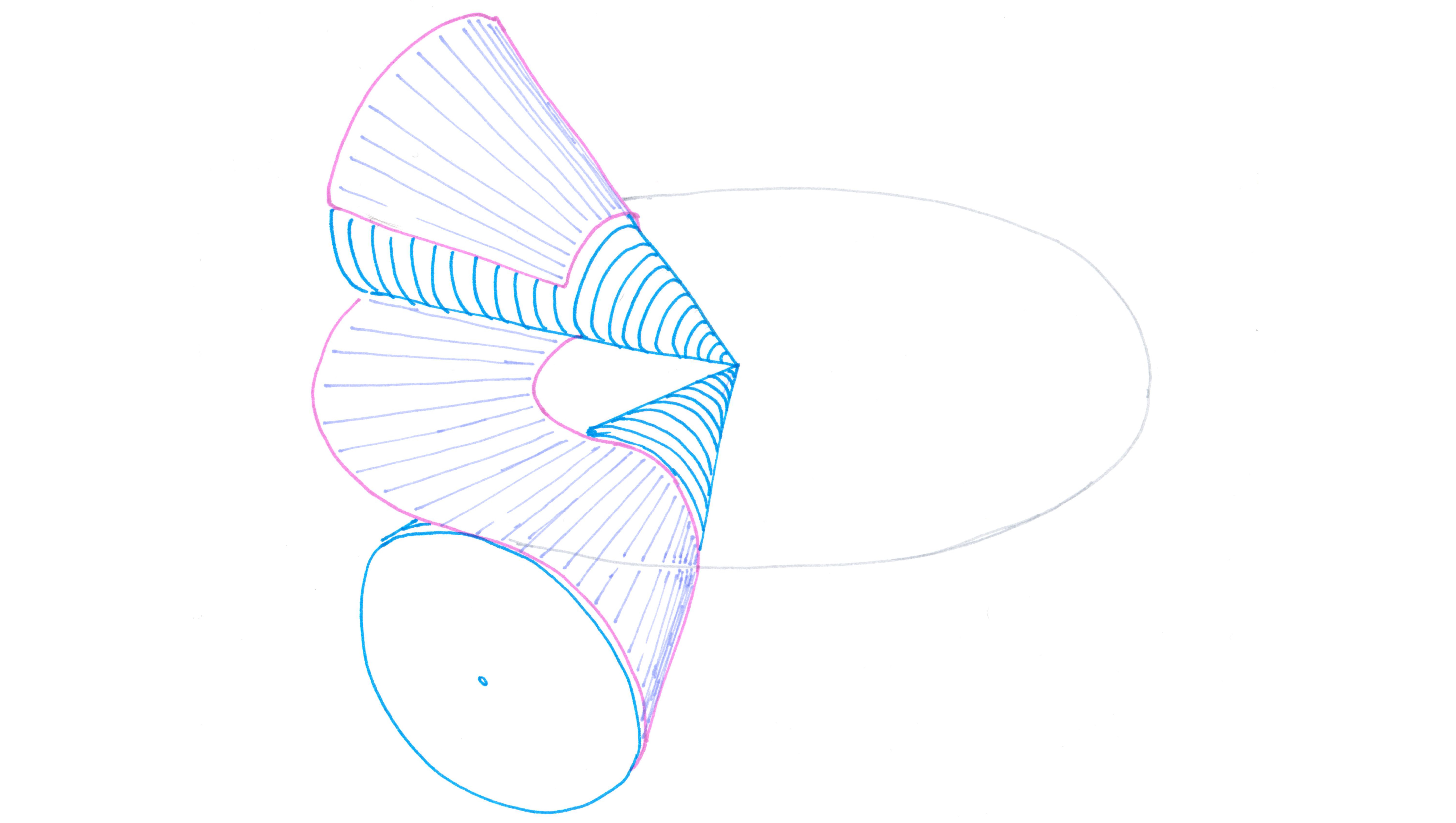
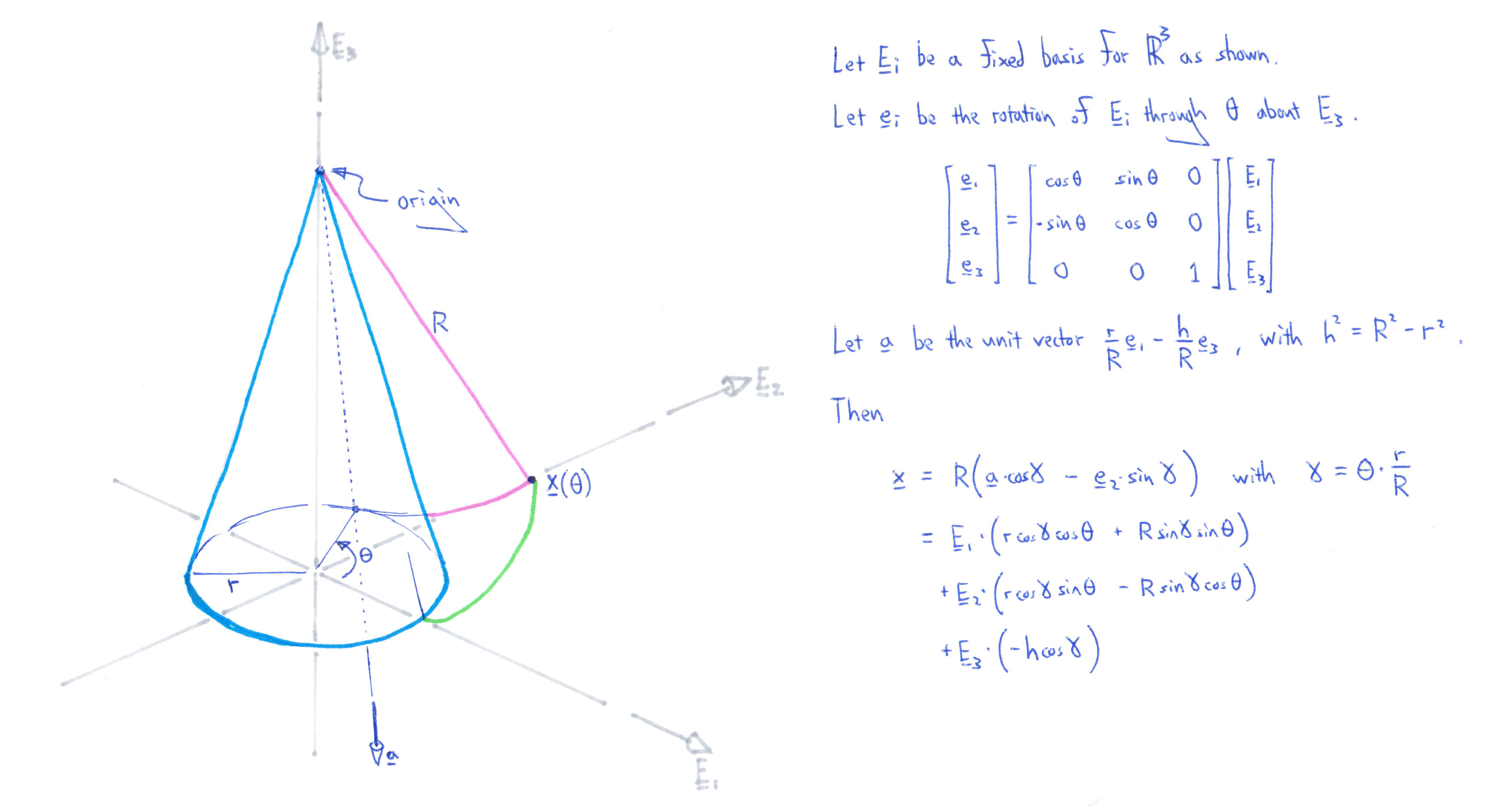
Previously we considered a point on the string connecting two disks. Here, we consider a line on the sheet of paper connecting the two cones. This line carves out a (ruled) surface as the paper unwraps from the cone. Here's my work for the path traced out by the tip of this line.
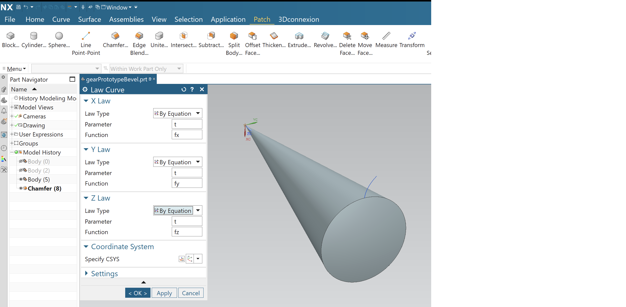
We get this curve into CAD using the same process as before. Here’s the expressions panel in NX.

As before, we construct a so called law curve in NX. Here I've also constructed the appropriate base cone.
We scale copy the curve with respect to the cone apex, and then use the Ruled tool to build the ruled surface bounded by the two curves.
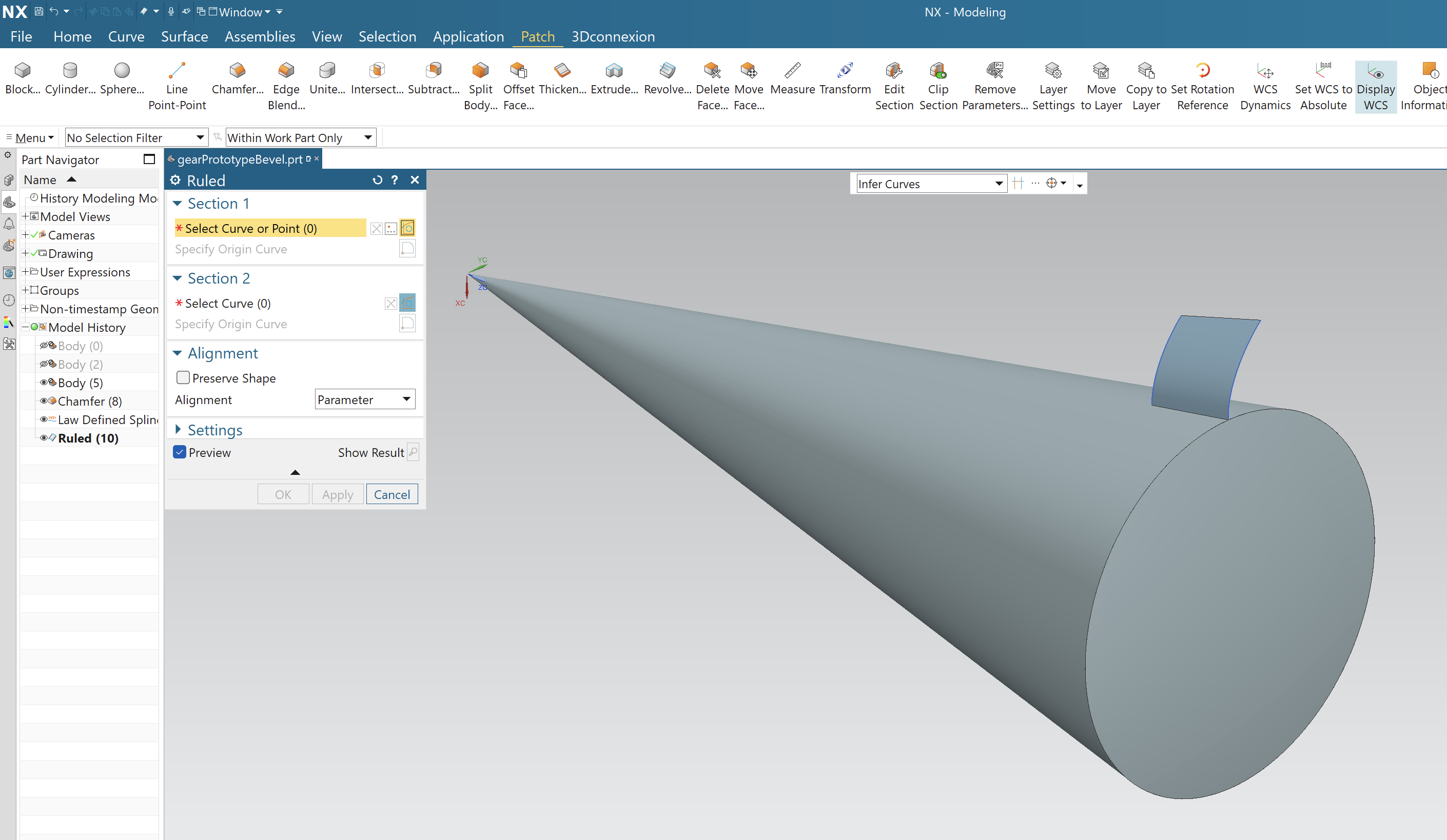
We use this ruled surface to split a solid body, creating the working surface of a bevel gear tooth. We then use reflections and rotations to create the full bevel gear.
Involute Gearing with non-Intersecting Axes
There is an analogous “involute” type construction in this case, in which the sheet body connecting the two base items is a kind of helicoid.
Higher Order Effects
In these notes I discuss the first order mathematics of involute gearing. There are all sorts of higher order effects and refinements that can be considered, but these can usually be ignored when initially scoping out a solution. If necessary, someone who specializes in gearing can add in these higher order effects without too much trouble later on.
Fabrication
With high enough resolution (e.g., HD3 from ProtoCafe as shown below), 3D printed gears can run together smoothly and serve as a useful development tool. For instance here's a contraption I built a few years ago.
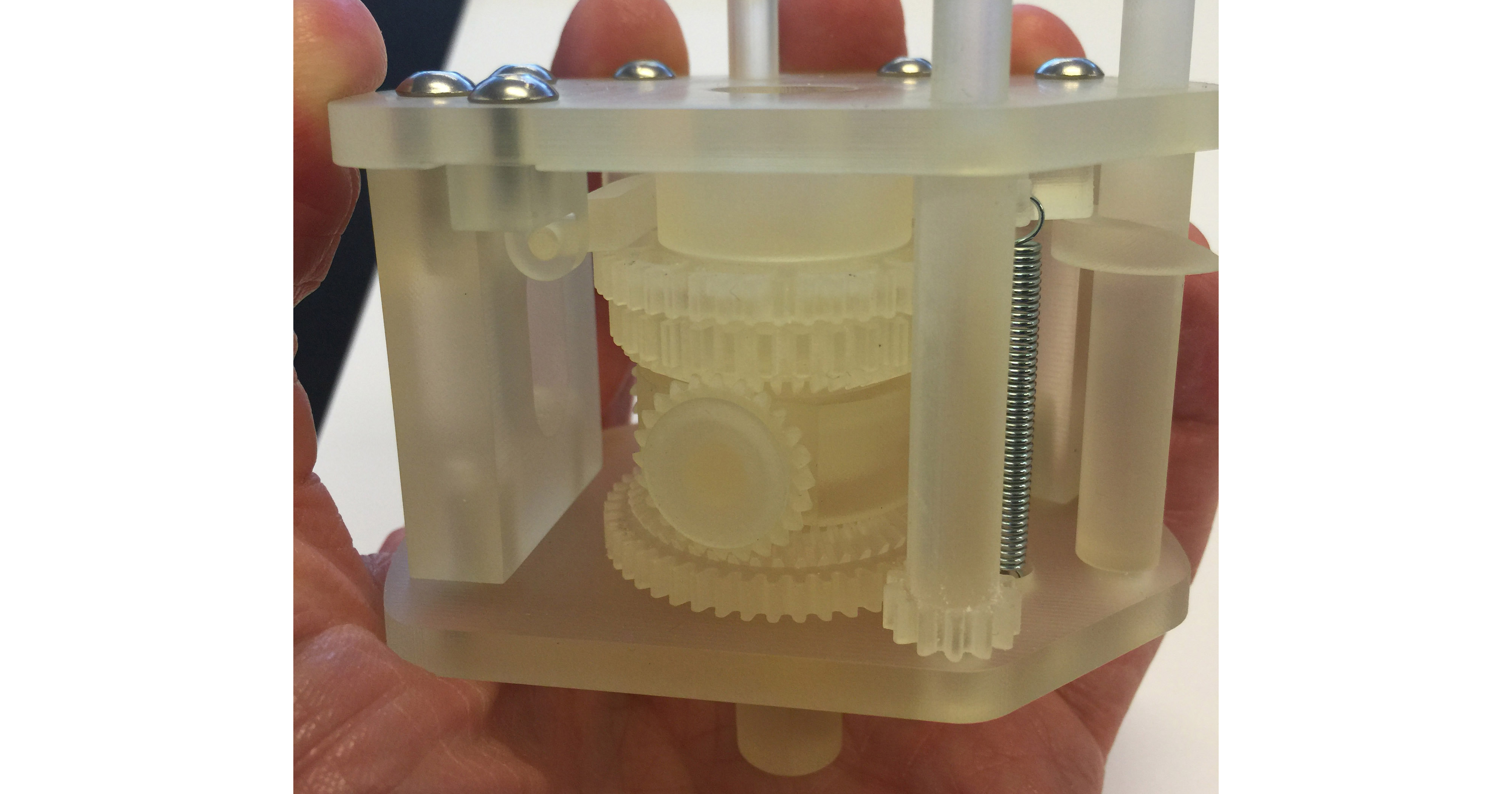
Gears capable of supporting higher loads and speeds typically need to be fabricated by different methods which we don’t focus on in this essay.
Reality Check
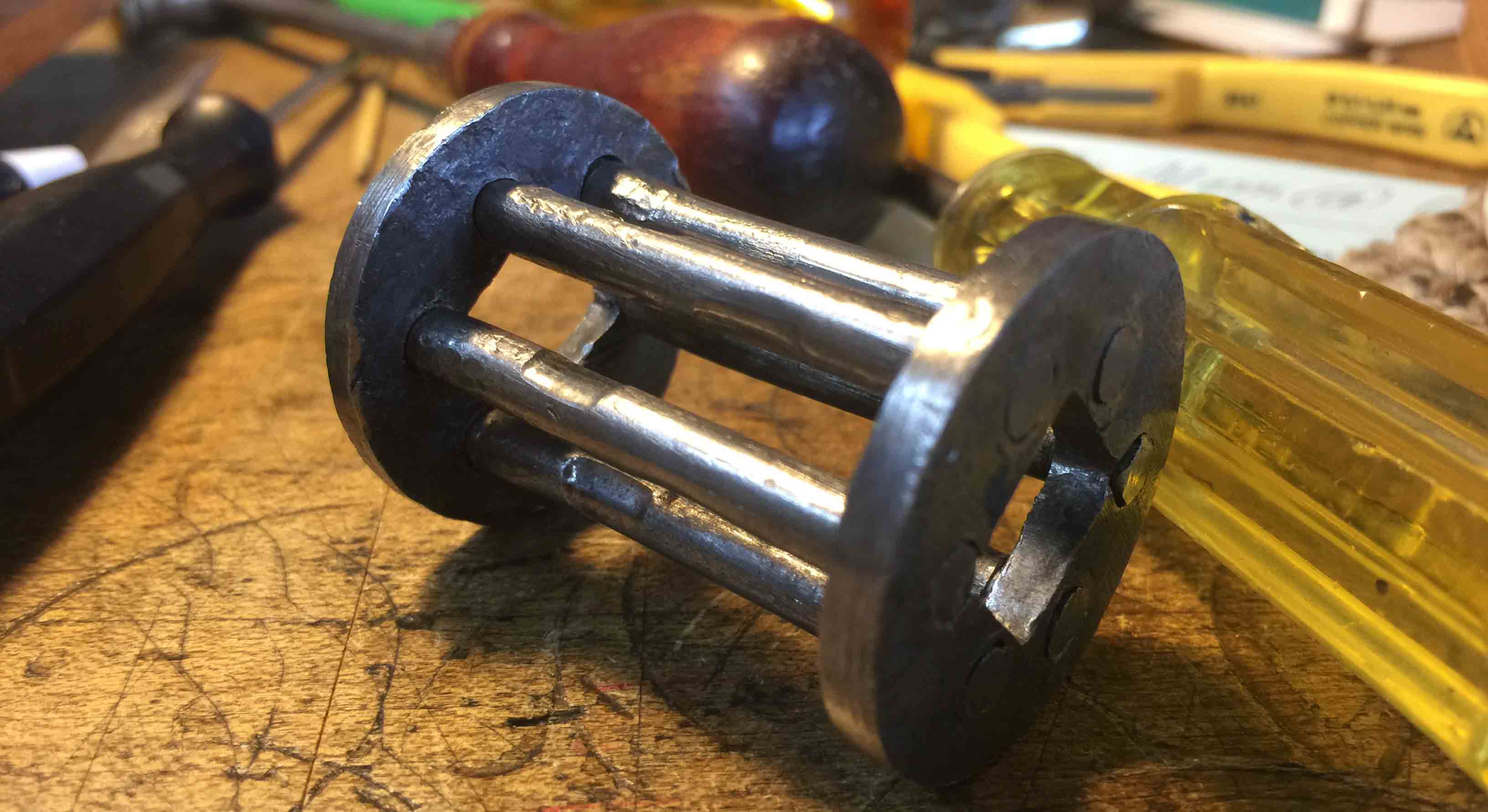
The following gear is from an 18th century tower clock. This is a great example of how real objects are typically riddled with dents and imperfections at every scale. In spite of these problems (not to mention the wear surfaces being cylindrical rather than involute) this gear worked well for centuries.
Resources
Gears are beautiful and ouroborically mesmerizing, and many people have published essays and videos exploring their properties. Some of my favorites are:
- Gears by Bartosz Ciechanowski.
- Involutometry by Van Gerpen and Reece.
- Three Gears are Possible by Henry Segerman.
- Involute Gears Explained by Gergely Bencsik.